Article
Beyond the Supplier’s Menu: Why Tooling Is a Strategy, Not a Transaction
Jeremiah Landi
- Product Development
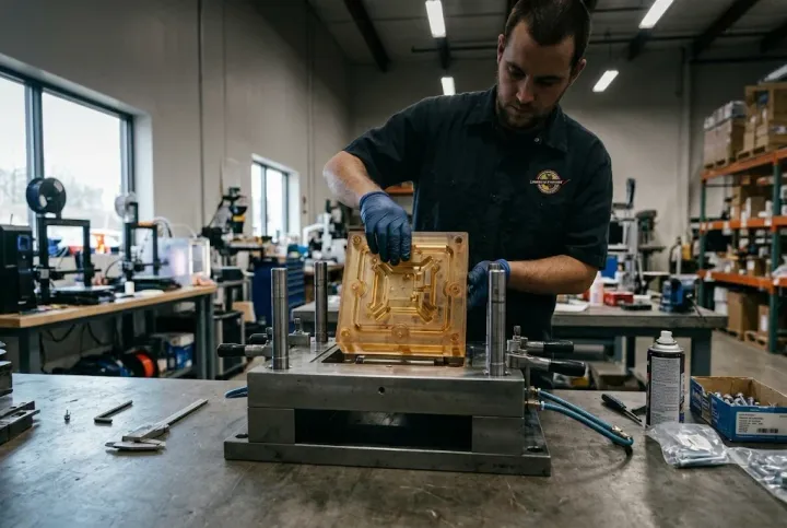
When we talk about “tooling,” we usually hear about it at the worst possible time: when we’re up against a deadline and staring at a massive quote.
Most suppliers present you with the options they happen to have in-house—whether that’s a $20,000 aluminum tool or a $100,000 steel production mold. We are often forced into a box based on a vendor’s equipment rather than our actual project needs.
This article is about high-pressure injection molding. While some of these concepts apply to low-pressure processes, comparing the two is like comparing soccer to baseball—they both use a ball, but they are entirely different games. High-pressure molding requires tools that can survive cavity pressures in the thousands of psi, clamping forces of tens to hundreds of tons, and the intense heat of molten resin [1]. To estimate the clamping force your own part needs, try our Clamping Force Calculator, which covers both injection molding and die casting. Resin casting, such as pouring urethane into silicone molds, can be a very viable alternative for low volumes, but it’s a different process with its own trade-offs, so I’m saving it for another article to keep this one focused.
In this environment, tooling shouldn’t be a “black box” transaction. It needs to be an open discussion from day one. The quality of your parts shapes how investors and customers react, and for those in the medical space, the FDA evaluates biocompatibility on the device in its final finished form, which means parts molded from the exact resin you plan to ship [2].
Part of that discussion is who owns the tool. I’m a firm believer that you, as the customer, should be ready to own your tooling. The most common setup is customer-owned tooling kept at the molder: you pay for the mold, you own it, and you can move it if the relationship doesn’t work out, though maintenance and replacement become your responsibility too [3]. The alternative is molder-financed tooling, where the cost is spread into your per-part price and the molder may keep ownership even after it’s paid off [3]. Paying the tooling invoice alone may not settle the question, so before any steel is cut, get title, transfer rights, storage, maintenance, and who can use or modify the mold in writing [4].
01 / Traditional tooling
1. Traditional Tooling: The Heavy Hitters
Traditional tooling relies on subtractive manufacturing to carve a mold out of a solid metal block. These tools generally fall into two categories:
- Production Tooling (Hardened Steel): Made from tool steels like P20 (pre-hardened) or H13 (hardened), these are the long-term choice for durability and precision. The top industry tier, SPI Class 101, is built for 1,000,000 cycles or more [5].
- Prototype Tooling (Aluminum): Using alloys like 7075, this is the usual bridge for prototype and low-volume runs, often in the thousands to tens of thousands of parts depending on resin and part design [5]. It’s faster to machine but “softer,” meaning it wears down over time.
Beyond One Part at a Time: Multi-Cavity and Family Molds
When people first get into injection molding, they often picture a simple one-to-one setup: the press closes, injects plastic, and drops a single part. Single-cavity molds are a good fit for prototypes, low volumes, and testing a part before committing to a bigger tool [6]. The big guys making consumer goods, packaging, or high-demand medical disposables rarely run one part per cycle.
Instead, production steel is usually built in one of two ways:
- Multi-Cavity Molds: The toolmaker machines several identical cavities, from a handful to dozens, into one mold base. Every cycle produces a batch of identical parts, which cuts press time and drives down the cost per part [6].
- Family Molds: Instead of copies of one part, a family mold holds the different pieces of an assembly, such as a device’s top shell, bottom shell, and battery door, so a matched set drops out of every cycle [6].
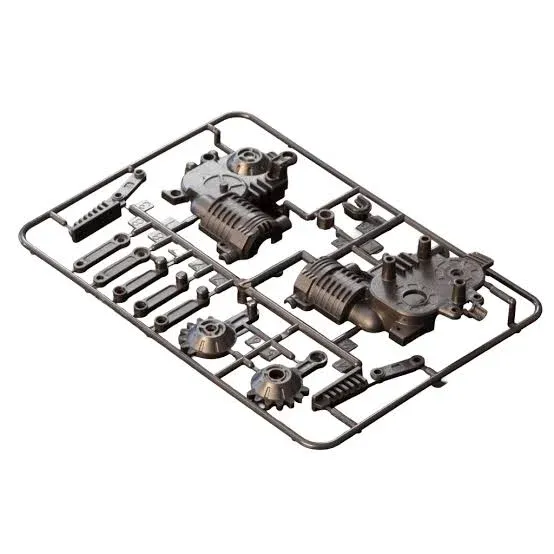
Multi-part tooling is how large operations get the most out of every press, but it raises the stakes upfront. The runner system has to be balanced so plastic fills every cavity evenly, family molds are especially hard to balance because the parts differ in size and shape, and you pay significantly more before the first part is ever molded [6].
The “Steel Safe” Reality of Metal Management
In traditional tooling, the design is never truly final, but changes are surgical. Modifying a metal mold involves a “steel safe” philosophy—it is always easier to take metal away than to add it.
- Removing Material: To enlarge a cavity or add a feature to the part, such as a rib or boss, you cut metal away by machining, grinding, or drilling (sometimes with a tool as simple as a Dremel).
- Adding Material: To shrink a cavity or remove a feature from the part, you have to add material back into the mold with welding, epoxy, or a temporary filler for quick checks.
Complex adjustments almost always need an experienced toolmaker so the mold still holds up under high molding pressure. On a multi-cavity tool, every change also has to be repeated identically in every cavity. That’s why it pays to design steel safe from the start: leave a little extra metal on critical dimensions, so your first round of changes means cutting metal away, not welding it back.
02 / 3D-printed tooling
2. 3D-Printed Tooling: The Speed Demon
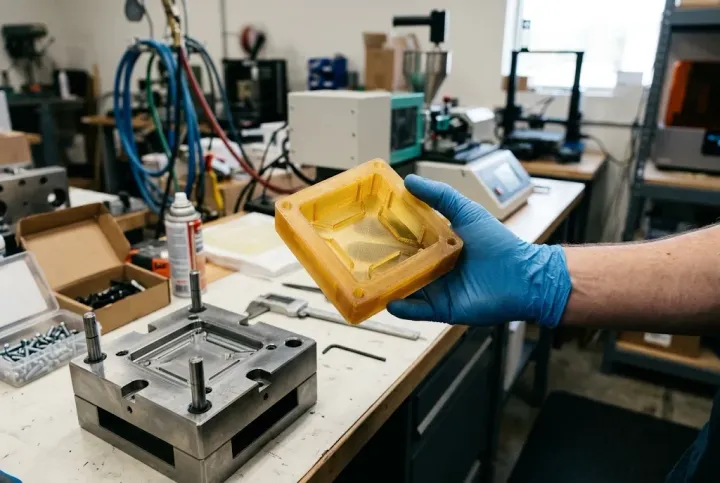
3D-printed tooling uses additive manufacturing, most commonly stereolithography (SLA) or Material Jetting, to produce mold cavities straight from a CAD file in days instead of the weeks CNC machining can take. Printing with a stiff, glass-filled resin like Formlabs Rigid 10K lets teams inject real thermoplastics such as polypropylene or ABS, rather than testing fragile printed prototypes [8]. Formlabs puts the sweet spot for printed molds at roughly 10 to 1,000 parts [9].
The Pushback: What Critics Point Out
Toolmakers and high-volume engineers are often skeptical of printed molds, and judged by mass-production standards, their concerns are fair. You get the tool faster, but each shot takes longer and the tool wears out sooner.
- Longer Cycle Times: Metal pulls heat out of molten plastic quickly, while printed resin acts as an insulator, so each part has to sit in the mold longer before ejection [8].
- The “Rounding” Effect: Printed resin can’t hold razor-sharp geometry for long. Sharp edges, tight internal corners, and thin ribs take the brunt of heat and pressure, so they chip or wear into rounded corners well before gentle curves do.
- Brittleness and Resin Limits: Stiff, glass-filled resins trade toughness for rigidity, so too much clamping force or a hot, viscous plastic can crack an insert mid-run. Formlabs’ own case studies show polycarbonate breaking Rigid 10K molds [10].
- Narrower Processing Window: Printed cavities don’t have the hardness or polish of steel, so technicians start with low injection pressure and speed, design in 2 to 5 degrees of draft, and often use mold release so parts don’t stick [8].
In my experience, finding a U.S. molder willing to run 3D-printed tooling is surprisingly hard. Most domestic shops are built around large, steady production orders, and a cracked insert ties up press time on a small batch.
We take that on because early product development is about learning fast, and cycle time matters much less. When a team is validating a new medical housing or testing how a snap-fit behaves in the real resin, waiting a few minutes per shot for 50 parts, or softening a few sharp corners with radii, is a small price compared with waiting weeks for machined tooling. The goal here is functional proximity: getting “close enough” to the final molded part in days so engineers can test in the real world, spot warpage or sink marks, and catch failure points early.
Two habits make it work: house the printed insert in a metal frame (more on that in section 4), and print a spare insert so one cools while the other runs [8]. Then you can tweak a wall thickness or move a gate and print a new cavity over a weekend, making your mistakes when a change costs a few hundred dollars rather than $50k to $100k in hardened steel.
03 / MUD quick-change tooling
3. MUD Tooling: The “Quick Change” Advantage
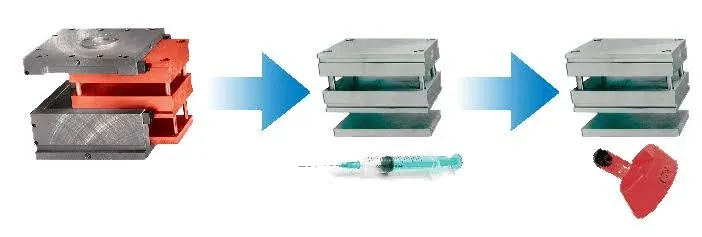
In traditional tooling, every part gets its own complete mold base: heavy steel plates, leader pins, bushings, and clamp plates bolted together as one unit [12]. A Master Unit Die (MUD) system splits that up. A universal steel frame stays bolted in the press, and only the smaller, part-specific inserts slide in and out. The defining feature is the Quick Change capability.
- Speed: Traditionally, changing a mold takes hours of unbolting plates, resetting the press, and reconnecting water lines. With a MUD system, you swap the internal inserts in minutes, and DME, which makes the system, says it cuts downtime by as much as 75% [13].
- Cost: DME says MUD can lower the initial cost of new tooling by as much as 66%, because you only buy the part-specific A and B inserts instead of a whole mold base every time [13]. The smaller inserts also take less time to machine and less room on the shelf.
MUD isn’t the answer for every part, and veteran toolmakers will tell you why. The insert has to fit a fixed pocket in the frame, so large parts and molds that need slides, lifters, or hydraulic core pulls often won’t fit, and ejection is usually limited to the frame’s standard pin layout [12]. For long-term, high-volume production, a dedicated mold can be more cost-effective [14]. Inserts are also built for one frame style, so if you ever move the tool, check that the new molder runs a matching frame.
We still lean into MUD because most product launches, especially in medical devices and high-mix industrial hardware, don’t start at five million units. They start with validation builds, clinical trials, cautious rollouts, and design tweaks. Tying up tens of thousands of dollars in a custom mold base before a product has proven itself slows teams down, and quick changeovers let us run smaller batches without burying customers in setup fees. If demand takes off, the geometry you’ve proven in the insert gives you a head start on a dedicated multi-cavity mold.
04 / The ideal hybrid
4. The Ideal Hybrid: 3D-Printed Inserts + MUD Frames
For early-stage hardware teams, the most strategic path is to combine additive speed with steel durability rather than choose between them. Nesting 3D-printed inserts inside a universal MUD frame creates a physical feedback loop that moves at the speed of software. Contract manufacturer Multiplus, for example, runs Formlabs Rigid 10K mold cores inside a metal mold shell for low-volume production [10].
- The Exoskeleton: A standalone printed mold struggles to survive the clamping force and injection pressure of a standard press. In a hybrid setup, the steel MUD frame acts as an exoskeleton, taking the brunt of the clamping force so the softer resin insert is less likely to flex or crack.
- Thermal Compensation: Printed resin is still a poor conductor of heat, but a steel MUD frame usually has its own water cooling lines. Nesting the insert in that cooled metal pocket draws heat out through the back and sides, and Formlabs notes a metal frame helps reduce cooling time [8]. It doesn’t remove the resin’s insulating effect, so cycles stay slower than in an all-metal mold, but it keeps heat from building up shot after shot. Resin limits from section 2 still apply.
- The FDA Advantage: Unlike a 3D-printed prototype part, a 3D-printed mold lets you inject the exact production-grade thermoplastic you plan to take to market. For medical devices that matters, because the FDA assesses biocompatibility on the device in its final finished form [2].
- Iterative Freedom: Because you aren’t fighting the “steel safe” battle of welding and grinding, design changes stay cheap. If a snap-fit needs adjusting or a wall causes sink marks, update the CAD file and print a revised insert for a few hundred dollars, keeping the conversation open until the geometry is locked for production steel.
05 / Aligning budget with reality
Conclusion: Aligning Your Budget with Reality
| Tooling strategy | Typical shot volume | Lead time | Upfront tooling cost | Best use case |
|---|---|---|---|---|
| 3D-Printed Tooling | 10–1,000 parts | Days | $ (Hundreds) | Rapid geometry validation and early material testing |
| Hybrid (3D Insert + MUD) | 50–1,000+ parts | Days to 1–2 weeks | $–$$ | Functional medical/FDA testing and fast design iteration |
| MUD Quick-Change (Metal) | 1,000–100,000+ parts | 2–5 weeks | $$ (Up to 66% less than full base) | Pilot runs, clinical builds, and high-mix, low-volume production |
| Traditional Steel (P20 / H13) | 100,000–Millions | 6–12+ weeks | $$$ ($50k–$100k+) | Frozen, high-volume mass production and multi-cavity scaling |
Combining 3D-printed inserts with a MUD frame is, for many hardware teams, the sweet spot of early-stage development. It lets you de-risk a product early, test in the finished production material the FDA looks for, and iterate faster than traditional machining allows.
You have to trust your engineering and manufacturing partners. If they tell you a part’s undercuts are too complex for a printed insert, a hot resin will crack a polymer core, or a critical tolerance needs hardened steel, listen to them. Manufacturing is a game of physics, and physics doesn’t care about your launch date.
Ultimately, smart tooling comes down to matching capital to certainty. Forcing a high-volume production outcome on a prototype budget leads to broken tools and missed deadlines. Spending $100k on hardened steel before a MUD or hybrid setup has proven the design in the real world is an unnecessary gamble.